Reference Instructions
|
Reference Instruction sheets can be downloaded from the table below. Instruction sheets are provided in PDF format for convenience and should be able to be viewed on nearly all platforms with a suitable PDF viewer application.
Track Components
| Sheet ID | Preview | Description | Pages | Rev | Pieces |
|---|---|---|---|---|---|
| 001 | 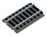
|
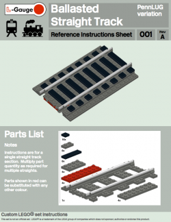
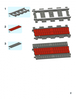
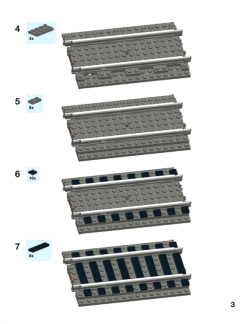
Ballasted Straight Track (PennLUG variation) Instructions to ballast a single full straight track element using the ballasting style first adopted by PennLUG. This finished track item is designed to mount on to a baseplate substrate with plates and tiles to secure the track section. Instructions for the baseplate substrate can be found in reference sheets 002 and 003. |
3 | A | 45 |
| Download Ref Sheet 001 Rev A | |||||
| 002 | 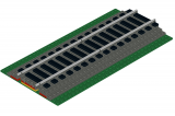
|
Ballasted Straight Track Baseplates (16x32) Instructions to make a substrate for straight ballasted track on a 16x32 baseplate. The baseplate colour as well as other items can be substituted as desired. |
1 | A | 19 |
| Download Ref Sheet 002 Rev A | |||||
| 003 | 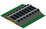
|
Ballasted Straight Track Baseplates (16x16) Instructions to make a substrate for straight ballasted track on a 16x16 baseplate. The baseplate colour as well as other items can be substituted as desired. |
1 | A | 35 |
| Download Ref Sheet 003 Rev A | |||||
| 004 | 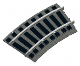
|
Ballasted R40 Curve Track (PennLUG variation) Instructions to ballast a single R40 curve track element using the ballasting style first adopted by PennLUG. This finished track item is designed to mount on to a baseplate substrate with plates and tiles to secure the track section. Instructions for the baseplate substrate can be found in reference sheet 005. |
4 | A | 62 |
| Download Ref Sheet 004 Rev A | |||||
| 005 | 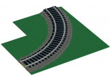
|
Ballasted R40 Curve Track Baseplates Instructions to make a baseplate substrate for a quarter circle R40 ballasted curve track. Part quantities can be multiplied as necessary to build a half or full circle. The baseplate colour as well as other items can be substituted as desired. |
22 | A | 245 |
| Download Ref Sheet 005 Rev A | |||||
| 006 | 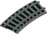
|
Ballasted R56 Curve Track (PennLUG variation) Instructions to ballast a single ME Models R56 curve track element using the ballasting style first adopted by PennLUG. This finished track item is designed to mount on to a baseplate substrate with plates and tiles to secure the track section. Ballasting method design contributed by Anthony Sava. |
4 | A | 70 |
| Download Ref Sheet 006 Rev A | |||||
| 007 | 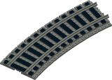
|
Ballasted R72 Curve Track (PennLUG variation) Instructions to ballast a single ME Models R72 curve track element using the ballasting style first adopted by PennLUG. This finished track item is designed to mount on to a baseplate substrate with plates and tiles to secure the track section. Ballasting method design contributed by Anthony Sava. |
5 | A | 86 |
| Download Ref Sheet 007 Rev A | |||||
| 008 | 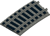
|
Ballasted R88 Curve Track (PennLUG variation) Instructions to ballast a single ME Models R88 curve track element using the ballasting style first adopted by PennLUG. This finished track item is designed to mount on to a baseplate substrate with plates and tiles to secure the track section. Ballasting method design contributed by Anthony Sava. |
6 | A | 66 |
| Download Ref Sheet 008 Rev A | |||||
| 009 | 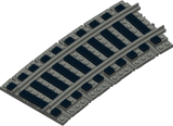
|
Ballasted R104 Curve Track (PennLUG variation) Instructions to ballast a single ME Models R104 curve track element using the ballasting style first adopted by PennLUG. This finished track item is designed to mount on to a baseplate substrate with plates and tiles to secure the track section. Ballasting method design contributed by Anthony Sava. |
11 | A | 87 |
| Download Ref Sheet 009 Rev A | |||||
| 010 | 
|
Ballasted R56 Curve Track Baseplates Instructions to make a baseplate substrate for a quarter circle R56 ballasted curve track. Part quantities can be multiplied as necessary to build a half or full circle. The baseplate colour as well as other items can be substituted as desired. |
21 | A | 332 |
| Download Ref Sheet 010 Rev A | |||||
| 011 | 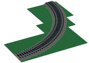
|
Ballasted R72 Curve Track Baseplates Instructions to make a baseplate substrate for a quarter circle R72 ballasted curve track. Part quantities can be multiplied as necessary to build a half or full circle. The baseplate colour as well as other items can be substituted as desired. |
22 | A | 428 |
| Download Ref Sheet 011 Rev A | |||||
| 012 | 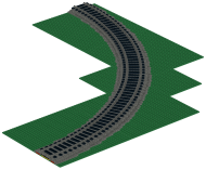
|
Ballasted R88 Curve Track Baseplates Instructions to make a baseplate substrate for a quarter circle R88 ballasted curve track. Part quantities can be multiplied as necessary to build a half or full circle. The baseplate colour as well as other items can be substituted as desired. |
25 | A | 437 |
| Download Ref Sheet 012 Rev A | |||||
| 013 | 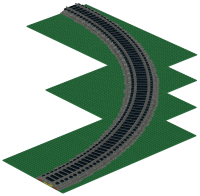
|
Ballasted R104 Curve Track Baseplates Instructions to make a baseplate substrate for a quarter circle R104 ballasted curve track. Part quantities can be multiplied as necessary to build a half or full circle. The baseplate colour as well as other items can be substituted as desired. |
29 | A | 505 |
| Download Ref Sheet 013 Rev A | |||||
| 014 | 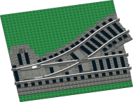
|
Ballasted Left Switch (even ties/sleepers) Instructions to make a ballasted left-hand track switch including the baseplate substrate. This variation has ties/sleepers located at even stud intervals. Instructions for odd stud intervals are contained in another reference sheet. Instructions for the baseplate substrate for the corresponding parallel return curve can be found in sheet 015. The baseplate colour as well as other items can be substituted as desired. |
20 | A | 277 |
| Download Ref Sheet 014 Rev A | |||||
| 015 | 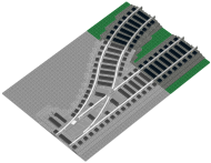
|
Ballasted Left Switch Return Curve Instructions to make a ballasted parallel return curve from a left-hand track switch. Instructions for the corresponding left switch can be found in sheet 014. The baseplate colour as well as other items can be substituted as desired. |
3 | A | 63 |
| Download Ref Sheet 015 Rev A | |||||
| 016 | 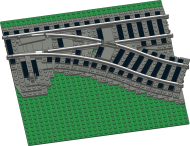
|
Ballasted Right Switch (even ties/sleepers) Instructions to make a ballasted right-hand track switch including the baseplate substrate. This variation has ties/sleepers located at even stud intervals. Instructions for odd stud intervals are contained in another reference sheet. Instructions for the baseplate substrate for the corresponding parallel return curve can be found in sheet 017. The baseplate colour as well as other items can be substituted as desired. |
20 | A | 278 |
| Download Ref Sheet 016 Rev A | |||||
| 017 | 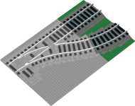
|
Ballasted Right Switch Return Curve Instructions to make a ballasted parallel return curve from a right-hand track switch. Instructions for the corresponding left switch can be found in sheet 016. The baseplate colour as well as other items can be substituted as desired. |
3 | A | 63 |
| Download Ref Sheet 017 Rev A | |||||
| 018 | 
|
Ballasted R120 Curve Track (PennLUG variation) Instructions to make a baseplate substrate for a quarter circle R120 ballasted curve track. Part quantities can be multiplied as necessary to build a half or full circle. The baseplate colour as well as other items can be substituted as desired. |
3 | B | 110 |
| Download Ref Sheet 018 Rev B | |||||
| 019 | 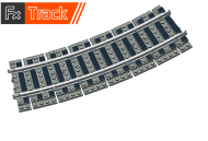
|
Ballasted R72 Curve Fx Track (8872) Instructions to ballast a single Fx Bricks brand R72 curve track element (Fx Track product 8872) using the PennLUG ballasting style. This finished track item is designed to mount on to a baseplate substrate with plates and tiles to secure the track section. |
6 | A | 100 |
| Download Ref Sheet 019 Rev A - Light Mode | |||||
| Download Ref Sheet 019 Rev A - Dark Mode | |||||
| 020 | 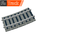
|
Ballasted R88 Curve Fx Track (8888) Instructions to ballast a single Fx Bricks brand R88 curve track element (Fx Track product 8888) using the PennLUG ballasting style. This finished track item is designed to mount on to a baseplate substrate with plates and tiles to secure the track section. |
7 | A | 57 |
| Download Ref Sheet 020 Rev A - Light Mode | |||||
| Download Ref Sheet 020 Rev A - Dark Mode | |||||
| 021 | 
|
Ballasted R104 Curve Track Instructions to ballast a single Fx Bricks brand R104 curve track element (Fx Track product 8904) or BrickTracks brand R104 (product R104PFDBG8) using the PennLUG ballasting style. This finished track item is designed to mount on to a baseplate substrate with plates and tiles to secure the track section. |
6 | A | 72 |
| Download Ref Sheet 021 Rev A - Light Mode | |||||
| Download Ref Sheet 021 Rev A - Dark Mode | |||||
| 022 | 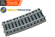
|
Ballasted R120 Curve Track Instructions to ballast a single Fx Bricks brand R120 curve track element (Fx Track product 8920) or BrickTracks brand R120 (product R120PFDBG8) using the PennLUG ballasting style. This finished track item is designed to mount on to a baseplate substrate with plates and tiles to secure the track section. |
7 | A | 99 |
| Download Ref Sheet 022 Rev A - Light Mode | |||||
| Download Ref Sheet 022 Rev A - Dark Mode |
Bogies / Trucks / Wheels
| Sheet ID | Preview | Description | Pages | Rev | Pieces |
|---|---|---|---|---|---|
| 100 | 
|
AAR 50 Ton Freight Truck Instructions to make a North American AAR 50 ton freight truck/bogie. This truck design requires the use of non-LEGO® brand brass tubes which are used to mount the train axle wheels. Suitable brass tubes can be obtained from K&S Metals (P/N 8127 or 9821). The train wheel assemblies can be either the older or newer variety (P/N 2878c01 or 2878c02); however the newer variety requires a new brass axle to be cut from 0.081" diameter brass rod (K&S Metals P/N 8168). Credit to Cale Leiphart and Dan Aubin for input on this design. |
4 | D | 51 |
| Download Ref Sheet 100 Rev D | |||||
| 101 | 
|
AAR Barber S-2 / ASF A-3 Freight Truck Instructions to make a North American 50 ton Barber S-2 or ASF A-3 freight truck/bogie. This freight truck depicts the solid axle bearing type with its distinctive journal boxes. This design of solid axle truck was introduced in the 1940s and were discontinued in 1966. All solid axle trucks were banned from service in 1980. This truck design requires the use of non-LEGO® brand brass tubes which are used to mount the train axle wheels. Suitable brass tubes can be obtained from K&S Metals (P/N 8127 or 9821). The train wheel assemblies can be either the older or newer variety (P/N 2878c01 or 2878c02); however the newer variety requires a new brass axle to be cut from 0.081" diameter brass rod (K&S Metals P/N 8168). Credit to Cale Leiphart and Josh Sanders for input on this design. |
4 | A | 58 |
| Download Ref Sheet 101 Rev A | |||||
| 102 | 
|
AAR 70 Ton Roller Bearing Freight Truck Instructions to make a North American 70 ton roller bearing freight truck/bogie. Since the discontinuation of solid axle trucks starting in 1966, all modern era freight cars use roller bearing axle trucks. This truck design requires the use of non-LEGO® brand brass tubes which are used to mount the train axle wheels. Suitable brass tubes can be obtained from K&S Metals (P/N 8127 or 9821). The train wheel assemblies can be either the older or newer variety (P/N 2878c01 or 2878c02); however the newer variety requires a new brass axle to be cut from 0.081" diameter brass rod (K&S Metals P/N 8168). Credit to Cale Leiphart and Josh Sanders for input on this design. |
4 | A | 54 |
| Download Ref Sheet 102 Rev A | |||||
| 103 | 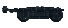
|
Osgood Bradley Passenger Coach Truck Instructions to make a North American Osgood Bradley lightweight passenger coach truck/bogie. This truck design requires the use of non-LEGO® brand brass tubes which are used to mount the train axle wheels. Suitable brass tubes can be obtained from K&S Metals (P/N 8127 or 9821). The train wheel assemblies can be either the older or newer variety (P/N 2878c01 or 2878c02); however the newer variety requires a new brass axle to be cut from 0.081" diameter brass rod (K&S Metals P/N 8168). Credit to Matt Csenge and Vinnie Fusca for input on this design. |
6 | A | 73 |
| Download Ref Sheet 103 Rev A | |||||
| 104 | 
|
3-Axle Heavyweight Passenger Coach Truck Instructions to make a North American 3-axle heavyweight passenger coach truck/bogie. This truck design requires the use of non-LEGO® brand brass tubes which are used to mount the train axle wheels. The centre axle must have free lateral movement of at least ±2mm in order to negotiate curves and switches. This can be achieved by cutting the brass axle bearing shorter than the outer fixed axle bearings. Suitable brass tubes can be obtained from K&S Metals (P/N 8127 or 9821). The train wheel assemblies can be either the older or newer variety (P/N 2878c01 or 2878c02); however the newer variety requires a new brass axle to be cut from 0.081" diameter brass rod (K&S Metals P/N 8168). Credit to Nate Brill, Matt Csenge and Vinnie Fusca for input on this design. |
5 | A | 61 |
| Download Ref Sheet 104 Rev A | |||||
| 105 | 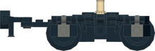
|
Sambre et Meuse European Freight Bogie Instructions to make a European freight bogie manufactured by Sambre et Meuse of France. This truck design requires the use of non-LEGO® brand brass tubes which are used to mount the train axle wheels. Suitable brass tubes can be obtained from K&S Metals (P/N 8127 or 9821). The train wheel assemblies can be either the older or newer variety (P/N 2878c01 or 2878c02); however the newer variety requires a new brass axle to be cut from 0.081" diameter brass rod (K&S Metals P/N 8168). Credit to Ronald Vallenduuk for this design. |
3 | A | 54 |
| Download Ref Sheet 105 Rev A | |||||
| 106 | Minden Deutz MD-36 European Passenger Bogie Instructions to make a MD-36 European passenger bogie manufactured by Minden Deutz. This truck design requires the use of non-LEGO® brand brass tubes which are used to mount the train axle wheels. Suitable brass tubes can be obtained from K&S Metals (P/N 8127 or 9821). The train wheel assemblies can be either the older or newer variety (P/N 2878c01 or 2878c02); however the newer variety requires a new brass axle to be cut from 0.081" diameter brass rod (K&S Metals P/N 8168). Credit to Ronald Vallenduuk for this design. |
5 | B | 78 | |
| Download Ref Sheet 106 Rev B |
MILS Train Modules
| Sheet ID | Preview | Description | Pages | Rev | Pieces |
|---|---|---|---|---|---|
| 200 | 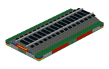
|
MILS Basic Terrain Module (BTM) Base for Single Track (16 x 32) Instructions to build a MILS compatible mounting base for ballasted straight single track. Instructions for the ballasted straight track sections can be found in reference sheet 001. |
6 | A | 100 |
| Download Ref Sheet 200 Rev A | |||||
| 201 | 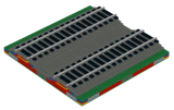
|
MILS Basic Terrain Module (BTM) Base for Double Track (32 x 32) Instructions to build a MILS compatible mounting base for ballasted straight double track. Instructions for the ballasted straight track sections can be found in reference sheet 001. |
8 | A | 175 |
| Download Ref Sheet 201 Rev A | |||||
| 202 | 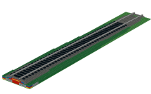
|
MILS Track Elevation Transition Set 3x (16 x 32) Instructions to build a set of 3 modules which act as both a functional and cosmetic transition between a MILS layout domain and a baseplate/tabletop domain. This transition provides a mounting base for ballasted straight track along a smooth nominal gradient of 1 plate/16 studs. Instructions for the ballasted straight track sections can be found in reference sheet 001. |
13 | A | 205 |
| Download Ref Sheet 202 Rev A | |||||
| 203 | 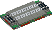
|
MILS Single Track Level Crossing (16 x 32) Instructions to build a single track level/grade crossing compatible with the MILS Single Track BTM base module (Ref Sheet 200). |
8 | A | 118 |
| Download Ref Sheet 203 Rev A | |||||
| 204 | 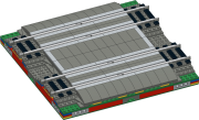
|
MILS Double Track Level Crossing (32 x 32) Instructions to build a double track level/grade crossing compatible with the MILS Double Track BTM base module (Ref Sheet 201). |
14 | A | 260 |
| Download Ref Sheet 204 Rev A |
MILS MultiRoad Modules
| Sheet ID | Preview | Description | Pages | Rev | Pieces |
|---|---|---|---|---|---|
| Road Module Bases | |||||
| 300 | 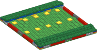
|
MILS MultiRoad Straight Road BTM Base 32 Instructions to build a MILS compatible mounting base for a 32 stud long straight road section compatible with adjacent Basic Terrain Modules (BTM). |
5 | A | 108 |
| Download Ref Sheet 300 Rev A | |||||
| 301 | 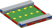
|
MILS MultiRoad Straight Road City Base 32 Instructions to build a MILS compatible mounting base for a 32 stud long straight road section with city sidewalks. |
7 | A | 192 |
| Download Ref Sheet 301 Rev A | |||||
| 302 | 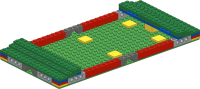
|
MILS MultiRoad Straight Road BTM Base 16 Instructions to build a MILS compatible mounting base for a 16 stud long straight road section compatible with adjacent Basic Terrain Modules (BTM). |
4 | A | 65 |
| Download Ref Sheet 302 Rev A | |||||
| 303 | 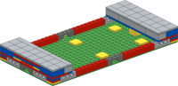
|
MILS MultiRoad Straight Road City Base 16 Instructions to build a MILS compatible mounting base for a 16 stud long straight road section with city sidewalks. |
6 | A | 107 |
| Download Ref Sheet 303 Rev A | |||||
| 304 | 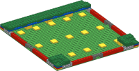
|
MILS MultiRoad T Junction Road BTM Base Instructions to build a MILS compatible mounting base for a T junction road section compatible with adjacent Basic Terrain Modules (BTM). |
6 | A | 104 |
| Download Ref Sheet 304 Rev A | |||||
| 305 | 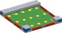
|
MILS MultiRoad T Junction Road City Base Instructions to build a MILS compatible mounting base for a T junction road section with city sidewalks. |
7 | A | 154 |
| Download Ref Sheet 305 Rev A | |||||
| 306 | 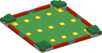
|
MILS MultiRoad X Junction Road BTM Base Instructions to build a MILS compatible mounting base for a X junction road section compatible with adjacent Basic Terrain Modules (BTM). |
6 | A | 100 |
| Download Ref Sheet 306 Rev A | |||||
| 307 | 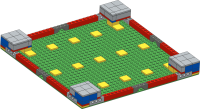
|
MILS MultiRoad X Junction Road City Base Instructions to build a MILS compatible mounting base for a X junction road section with city sidewalks. |
6 | A | 116 |
| Download Ref Sheet 307 Rev A | |||||
| 308 | 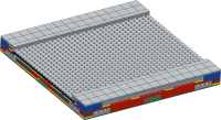
|
MILS MultiRoad Cobblestone Road 32 Instructions to build a MILS compatible cobblestone road surface on a specialized 32 x 32 base. The sidewalks and road dimensions are compatible with MultiRoad City modules. Thanks to Ludo Soete for contributing these instructions. |
11 | A | 1317 |
| Download Ref Sheet 308 Rev A | |||||
| 309 | 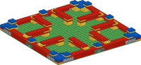
|
MILS MultiRoad Modular Building Adapter Base 32 Instructions to build a MILS compatible mounting base to seamlessly integrate 32 x 32 LEGO® Modular Buildings into a MILS layout using MultiRoad City bases. |
5 | A | 129 |
| Download Ref Sheet 309 Rev A | |||||
| Roadway Lane Modules | |||||
| 310 | 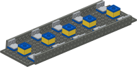
|
MILS MultiRoad Left Lane 32 Instructions to build a 32 stud left lane section for a MultiRoad base module. |
3 | A | 45 |
| Download Ref Sheet 310 Rev A | |||||
| 311 | 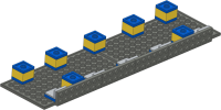
|
MILS MultiRoad Right Lane 32 Instructions to build a 32 stud right lane section for a MultiRoad base module. |
3 | A | 37 |
| Download Ref Sheet 311 Rev A | |||||
| 312 | 
|
MILS MultiRoad Left Lane 16 Instructions to build a 16 stud left lane section for a MultiRoad base module. |
2 | A | 26 |
| Download Ref Sheet 312 Rev A | |||||
| 313 | 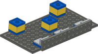
|
MILS MultiRoad Right Lane 16 Instructions to build a 16 stud right lane section for a MultiRoad base module. |
2 | A | 18 |
| Download Ref Sheet 313 Rev A | |||||
| 314 | 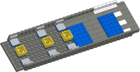
|
MILS MultiRoad Left Crosswalk 32 Instructions to build a 32 stud left lane section which includes a pedestrian crossing for a MultiRoad base module. |
9 | A | 58 |
| Download Ref Sheet 314 Rev A | |||||
| 315 | 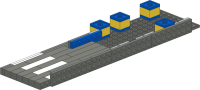
|
MILS MultiRoad Right Crosswalk 32 Instructions to build a 32 stud right lane section which includes a pedestrian crossing for a MultiRoad base module. |
5 | A | 52 |
| Download Ref Sheet 315 Rev A | |||||
| Roadway Stripes and Markings | |||||
| 319 | 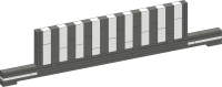
|
MILS MultiRoad T Junction Crosswalk Instructions to build a T junction road segment with a crosswalk. This can be used with any of the T and X junction road sections. This segment mounts to either a left or right lane module in the same way as a line marking section does. |
4 | A | 72 |
| Download Ref Sheet 319 Rev A | |||||
| 320 | 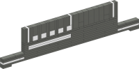
|
MILS MultiRoad Junction Road Segment Instructions to build a junction road segment which can be used with any of the T and X junction road sections. This segment mounts to either a left or right lane module in the same way as a line marking section does. |
6 | A | 90 |
| Download Ref Sheet 320 Rev A | |||||
| 321 | 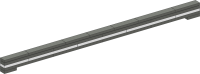
|
MILS MultiRoad Solid White Line 32 Instructions to build a 32 stud solid white line marking which can be mounted to either the left, centre or right lane positions. |
2 | A | 22 |
| Download Ref Sheet 321 Rev A | |||||
| 322 | 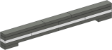
|
MILS MultiRoad Solid White Line 16 Instructions to build a 16 stud solid white line marking which can be mounted to either the left, centre or right lane positions. |
2 | A | 12 |
| Download Ref Sheet 322 Rev A | |||||
| 323 | 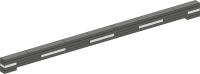
|
MILS MultiRoad Dashed White Line 32 Instructions to build a 32 stud dashed white line marking which can be mounted to either the left, centre or right lane positions. |
3 | A | 27 |
| Download Ref Sheet 323 Rev A | |||||
| 324 | 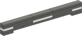
|
MILS MultiRoad Dashed White Line 16 Instructions to build a 16 stud dashed white line marking which can be mounted to either the left, centre or right lane positions. |
2 | A | 15 |
| Download Ref Sheet 324 Rev A | |||||
| 325 | 
|
MILS MultiRoad Double Yellow Line 32 Instructions to build a 32 stud double yellow line marking which can be mounted to either the left, centre or right lane positions. |
2 | A | 23 |
| Download Ref Sheet 325 Rev A | |||||
| 326 | 
|
MILS MultiRoad Double Yellow Line 16 Instructions to build a 16 stud double yellow line marking which can be mounted to either the left, centre or right lane positions. |
2 | A | 13 |
| Download Ref Sheet 326 Rev A | |||||
| 328 | 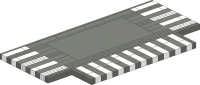
|
MILS MultiRoad X Junction Left Lane Instructions to build the left lane side of a X junction with pedestrian crosswalks on all 4 routes of the junction. Combine with sheet 329 to make a complete junction. |
11 | A | 177 |
| Download Ref Sheet 328 Rev A | |||||
| 329 | 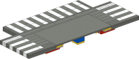
|
MILS MultiRoad X Junction Right Lane Instructions to build the right lane side of a X junction with pedestrian crosswalks on all 4 routes of the junction. Combine with sheet 328 to make a complete junction. |
8 | A | 139 |
| Download Ref Sheet 329 Rev A | |||||
| Roadway Entrances and Parking | |||||
| 330 | 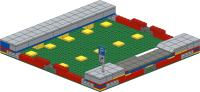
|
MILS MultiRoad X Laneway Entrance Instructions to build a laneway or driveway entrance off of a main road. The lane entrance can be used to transition to a parking lot, a driveway to a building or a minor roadway. Instructions generously contributed by Ludo Soete. |
8 | A | 213 |
| Download Ref Sheet 330 Rev A | |||||
| 331 | 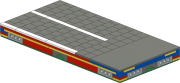
|
MILS MultiRoad Parking Lot Left Side Markings Instructions to build a modular parking lot section with left hand separator markings. Combine multiple modules to make a parking lot of a desired size. This module can be oriented either horizontally or vertically with respect to the entrance to the main road. Modules can also be stacked for multiple rows or columns within a parking lot. Instructions generously contributed by Ludo Soete. |
5 | A | 208 |
| Download Ref Sheet 331 Rev A | |||||
| 332 | 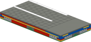
|
MILS MultiRoad Parking Lot Right Side Markings Instructions to build a modular parking lot section with right hand separator markings. Combine multiple modules to make a parking lot of a desired size. This module can be oriented either horizontally or vertically with respect to the entrance to the main road. Modules can also be stacked for multiple rows or columns within a parking lot. Instructions generously contributed by Ludo Soete. |
5 | A | 208 |
| Download Ref Sheet 332 Rev A | |||||
| 333 | 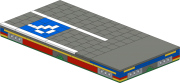
|
MILS MultiRoad Parking Lot Left with Disabled Space Instructions to build a modular parking lot section with left hand separator markings and a dedicated space for disabled parking. Combine multiple modules to make a parking lot of a desired size. This module can be oriented either horizontally or vertically with respect to the entrance to the main road. Modules can also be stacked for multiple rows or columns within a parking lot. Instructions generously contributed by Ludo Soete. |
7 | A | 220 |
| Download Ref Sheet 333 Rev A | |||||
| 334 | 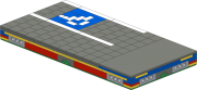
|
MILS MultiRoad Parking Lot Right with Disabled Space Instructions to build a modular parking lot section with right hand separator markings and a dedicated space for disabled parking. Combine multiple modules to make a parking lot of a desired size. This module can be oriented either horizontally or vertically with respect to the entrance to the main road. Modules can also be stacked for multiple rows or columns within a parking lot. Instructions generously contributed by Ludo Soete. |
7 | A | 220 |
| Download Ref Sheet 334 Rev A | |||||
ViaTrack System Components

| Sheet ID | Preview | Description | Pages | Rev | Pieces |
|---|---|---|---|---|---|
| Track Modules | |||||
| 410 | 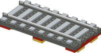
|
ViaTrack Ballasted Concrete Tie/Sleeper Track Instructions to build a typical ballasted concrete tie/sleeper track section. This track assembly can be directly mounted to the track frame module Ref 440. |
2 | A | 54 |
| Download Ref Sheet 410 Rev A | |||||
| 411 | 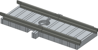
|
ViaTrack Flat Slab Concrete Track Instructions to build a solid slab concrete track assembly. This assembly is designed to fit the track mounting base Ref 421. The combined assembly can then be mounted to the track frame module Ref 440. |
2 | A | 37 |
| Download Ref Sheet 411 Rev A | |||||
| 412 | 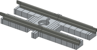
|
ViaTrack Open Slab Concrete Track Instructions to build an open frame slab concrete track assembly. This assembly is designed to fit the track mounting base Ref 422 or Ref 423. The combined assembly can then be mounted to the track frame module Ref 440. |
2 | A | 60 |
| Download Ref Sheet 412 Rev A | |||||
| 421 | 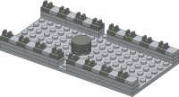
|
ViaTrack Flat Slab Track Base Instructions to build a mounting base for the flat slab concrete track assembly Ref 411. The combined assembly can be mounted to the track frame module Ref 440. |
2 | A | 48 |
| Download Ref Sheet 421 Rev A | |||||
| 422 | 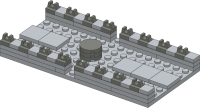
|
ViaTrack Open Frame Track Base Concrete Instructions to build a mounting base for the open frame concrete track assembly Ref 412. The combined assembly can be mounted to the track frame module Ref 440. |
2 | A | 53 |
| Download Ref Sheet 422 Rev A | |||||
| 423 | 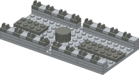
|
ViaTrack Open Frame Track Base Ballasted Instructions to build a mounting base for the open frame concrete track assembly Ref 412. The combined assembly can be mounted to the track frame module Ref 440. |
2 | A | 53 |
| Download Ref Sheet 423 Rev A | |||||
| 440 | 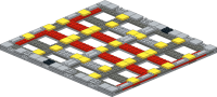
|
ViaTrack Mounting Frame for Double Track Instructions to build a mounting frame which is used to support track sections, cosmetic track borders and clip-in wall sections. The mounting frame can be freely mounted to a supporting viaduct structure below. |
6 | B | 178 |
| Download Ref Sheet 440 Rev B | |||||
| Track Border Panels | |||||
| 450 | 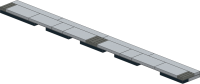
|
ViaTrack Concrete Track Border Instructions to build a concrete track border panel (3 x 32). |
2 | A | 24 |
| Download Ref Sheet 450 Rev A | |||||
| 451 | 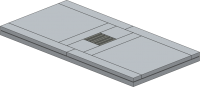
|
ViaTrack Concrete Track Centre Instructions to build a centre concrete track border panel (8 x 16). |
2 | A | 13 |
| Download Ref Sheet 451 Rev A | |||||
| 452 | 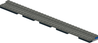
|
ViaTrack Ballast Track Border Instructions to build a ballasted track border panel (3 x 32). |
2 | A | 23 |
| Download Ref Sheet 452 Rev A | |||||
| 453 | 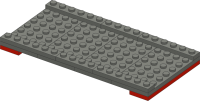
|
ViaTrack Ballasted Track Centre Instructions to build a centre ballasted track border panel (8 x 16). |
2 | A | 14 |
| Download Ref Sheet 453 Rev A | |||||
| Clip-in Cosmetic Wall Modules | |||||
| 460 | 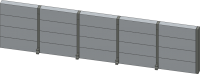
|
ViaTrack Concrete Panelled Wall Section Instructions to build a concrete panelled wall section. This wall assembly can be clipped to either side of the track frame Ref 440 assembly. |
2 | A | 33 |
| Download Ref Sheet 460 Rev A | |||||
| 461 | 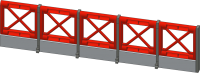
|
ViaTrack Open Girder Wall Section Instructions to build a open girder wall section. This wall assembly can be clipped to either side of the track frame Ref 440 assembly. |
2 | A | 23 |
| Download Ref Sheet 461 Rev A | |||||
| 463 | 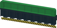
|
ViaTrack Girder Bridge Sides Instructions to build cosmetic girder bridge side walls designed to clip to either side of the track frame Ref 440 assembly. This bridge assembly can be customized by building in different colours or by substituting or removing the hazard strip. |
13 | A | 170 |
| Download Ref Sheet 463 Rev A | |||||
| 464 | 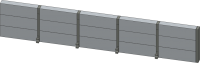
|
ViaTrack Short Concrete Panelled Wall Section Instructions to build a short concrete panelled wall section. This wall assembly can be clipped to either side of the track frame Ref 440 assembly. |
2 | A | 28 |
| Download Ref Sheet 464 Rev A | |||||
| Viaduct Structures | |||||
| 470 | 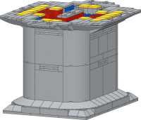
|
ViaTrack Poured Concrete Viaduct Instructions to build a poured concrete viaduct pier. This viaduct section is designed to support a track mounting frame above. |
12 | A | 316 |
| Download Ref Sheet 470 Rev A | |||||
| 471 | 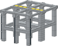
|
ViaTrack Precast Concrete Viaduct Instructions to build a typical open-frame pre-cast concrete viaduct. This viaduct section is designed to support a track mounting frame above. The side facing 2x2 tile elements can be removed to add trackside accessories such as overhead line gantries, signals, lights, signs, etc. |
16 | A | 346 |
| Download Ref Sheet 471 Rev A | |||||