Difference between revisions of "Modular Standards"
| Line 67: | Line 67: | ||
I have designed a system which I have called "MultiRoad". It is a system of modular components specifically designed for making MILS compatible roadways. It has three main components: | I have designed a system which I have called "MultiRoad". It is a system of modular components specifically designed for making MILS compatible roadways. It has three main components: | ||
| − | 1 | + | 1. MILS compliant base modules of 32x32 studs |
| − | 2 | + | |
| − | 3 | + | 2. Generic roadway sections representing "left" and "right" lanes. |
| + | |||
| + | 3. Interchangeable 5-plate strips mounted to the left, centre and right sections of the roadway. These strips allow for the customization of the roadway appearance to represent almost any region-specific roadway markings. | ||
The roadway surface is a nominal 6 plates above baseplate height. This allows for a gentle drainage slope away from the road and more importantly, allows roadway markings and features to be rendered SNOT wise within a 2 stud space resting on tiles. Also, this height blends nicely to self contained railway level crossings requiring only a 3 plate incline to rail height. | The roadway surface is a nominal 6 plates above baseplate height. This allows for a gentle drainage slope away from the road and more importantly, allows roadway markings and features to be rendered SNOT wise within a 2 stud space resting on tiles. Also, this height blends nicely to self contained railway level crossings requiring only a 3 plate incline to rail height. | ||
Revision as of 18:05, 18 September 2017
MILS
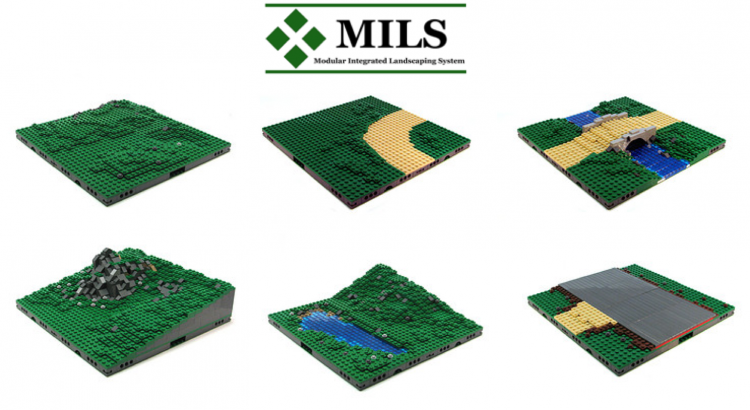
MILS: Modular Integrated Landscaping System. This standard has been developed by members of the HispaLUG/HispaBrick community for collaborative diorama displays. Among its key features is that it is simple and flexible and can be used with many different LEGO® themes besides trains.
MILS Structure
The MILS standard is primarily based on 32x32 baseplates; however, intermediate sizes of 16x32 can be used as long as its terrain features share a common profile with adjacent modules. Ground level is 1 brick (3 plates) above the baseplate reference level. Modules interconnect with Technic pins into 1x4 Technic bricks located at module corners. Typically the 2x2 corner space is used as an identification feature. This identification can be used by a builder to show ownership or it can be used as guide for orientation between adjacent modules.
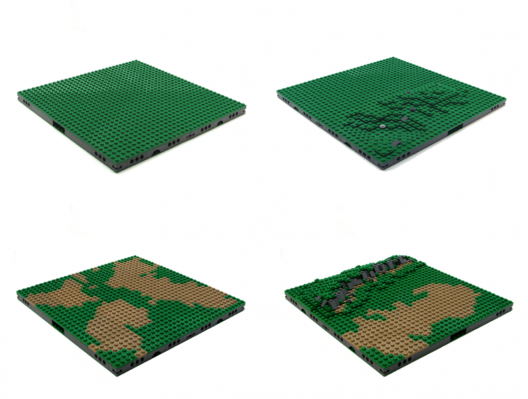
MILS Basic Terrain Modules (BTM)
MILS BTM modules have so-called "null" profile, i.e. no contours at the edges.
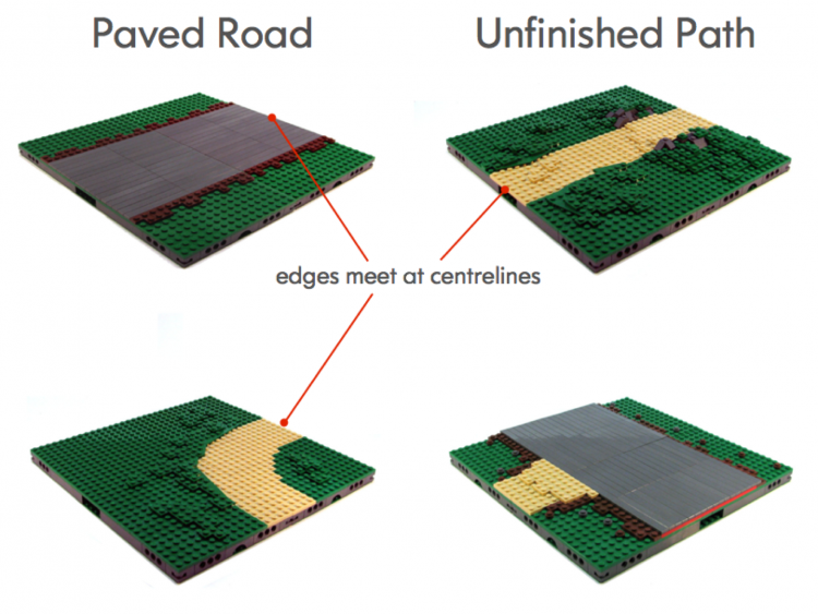
MILS BTM with Roads
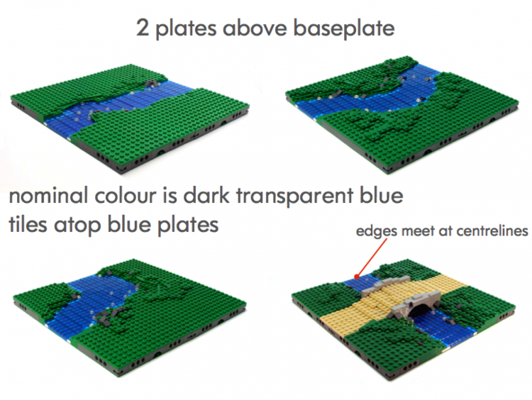
MILS BTM with Water Features
Water features are rendered at 2 plates above the baseplate. The bottom layer is typically blue or green colour plates with a top layer of transparent tiles, often using dark transparent blue.
MILS Contour Terrain Modules (CTM)
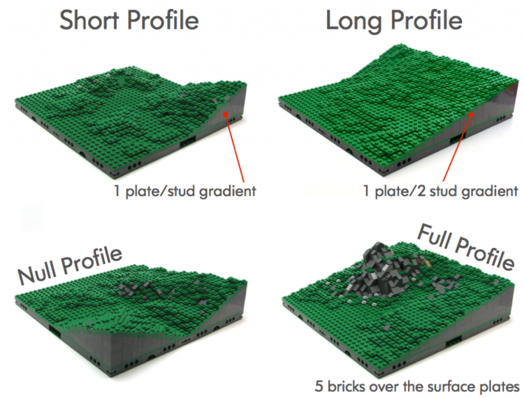
MILS contours are specified as either a "Short Profile" or "Long Profile". Short Profile contours are nominally 1 plate per stud gradient whereas Long Profile contours are 1 plate per 2 stud gradient. So-called "null" profiles are at ground level whereas "Full Profiles" are 5 bricks (15 plates) above ground level.
MILS Train Modules
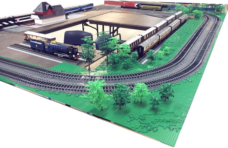
MILS modules form an excellent foundation for mounting track and building a complete layout. MILS modules form a rigid box structure which provides a stable and flat surface to mount track sections.
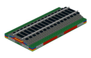
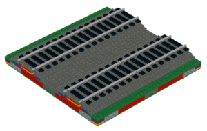
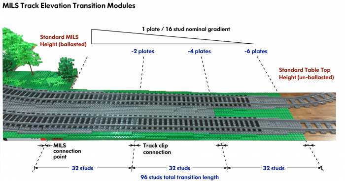
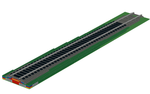
For layouts which need to transition to sections of the layout built at the conventional height of a baseplate, a set of 3 modules can be built which act as both a functional and cosmetic transition between a MILS layout domain and a baseplate/tabletop domain. This transition provides a mounting base for ballasted straight track along a smooth nominal gradient of 1 plate/16 studs.
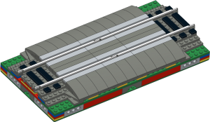
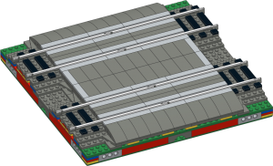
Level crossings over roadways can built in a modular fashion and fully self-contained within a single MILS module.
MILS Links
For additional information on MILS, please refer to these links:
MultiRoad: Modular Road System for MILS
The MILS standard describes terrain and landforms very well and shows many inspiring examples of landscape modules. One area of the standard which I felt needed more detail and greater scope was roads.
Many layouts will require some form of roadway. This also includes airport runways/taxiways--an area often forgotten. Furthermore, the roadways must seamlessly integrate with adjacent landforms, include infrastructure such as sidewalks for areas next to buildings and lastly integration with railway modules.
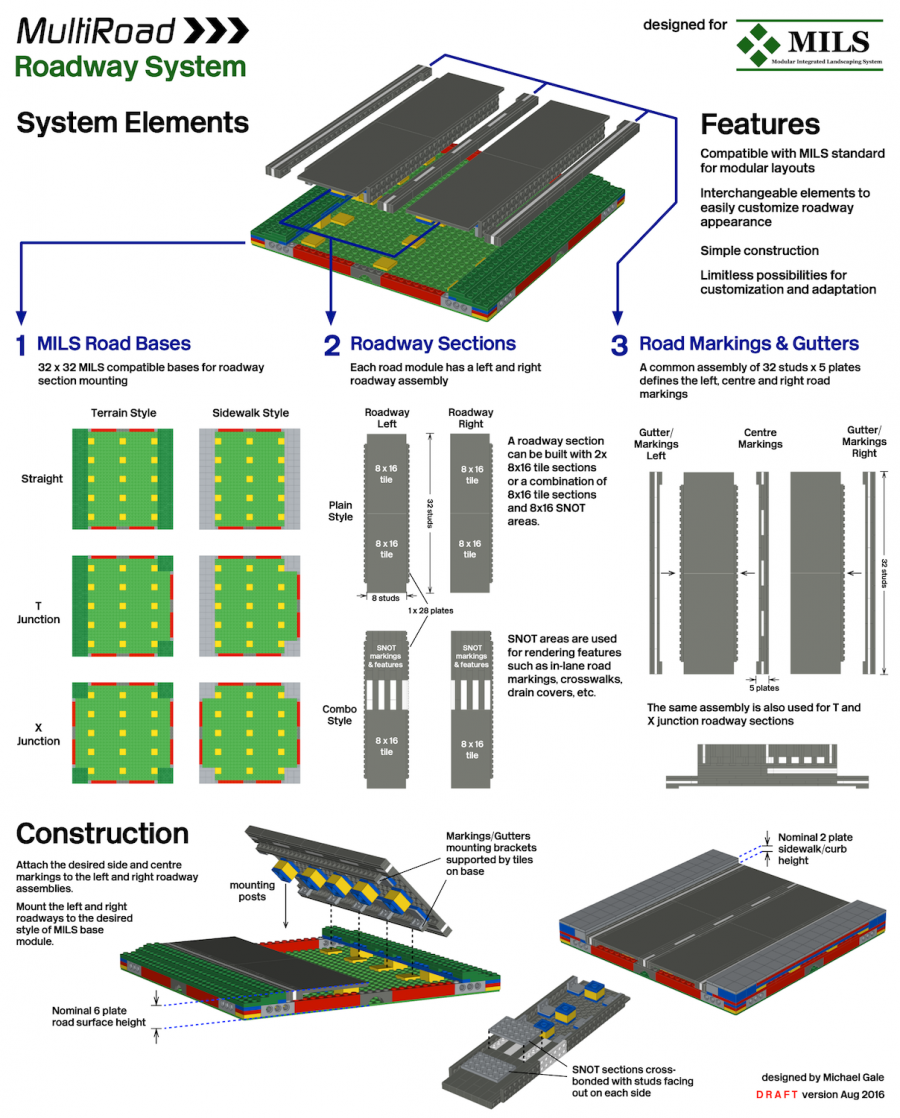
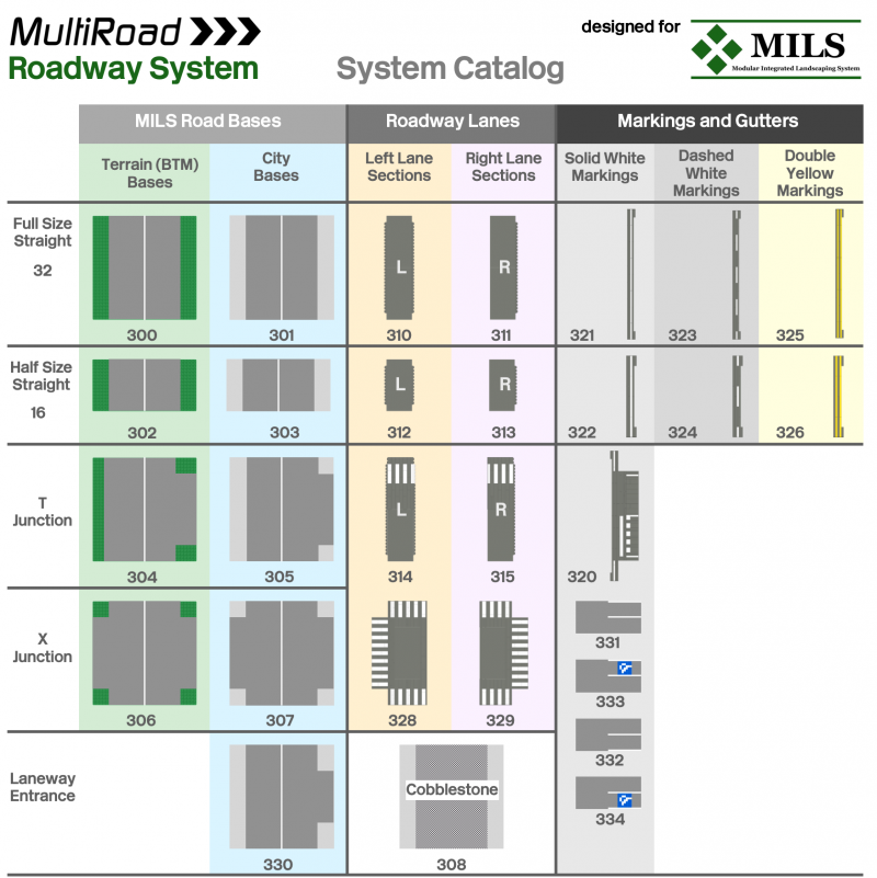
I have designed a system which I have called "MultiRoad". It is a system of modular components specifically designed for making MILS compatible roadways. It has three main components:
1. MILS compliant base modules of 32x32 studs
2. Generic roadway sections representing "left" and "right" lanes.
3. Interchangeable 5-plate strips mounted to the left, centre and right sections of the roadway. These strips allow for the customization of the roadway appearance to represent almost any region-specific roadway markings.
The roadway surface is a nominal 6 plates above baseplate height. This allows for a gentle drainage slope away from the road and more importantly, allows roadway markings and features to be rendered SNOT wise within a 2 stud space resting on tiles. Also, this height blends nicely to self contained railway level crossings requiring only a 3 plate incline to rail height.
MultiRoad System Catalog
The MultiRoad system basically involves combining the different elements together for a desired road configuration. All of the elements are designed to be interchangeable and can of course be customized further.
Instructions for all of these elements can be found in the Reference Instructions section.
ViaTrack: Modular System For Elevated Railway
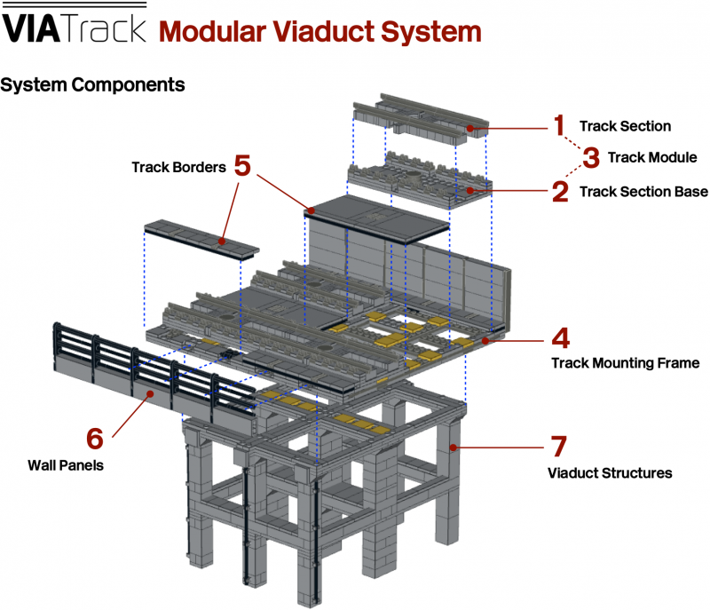
ViaTrack is a modular system for building elevated railways on viaducts.
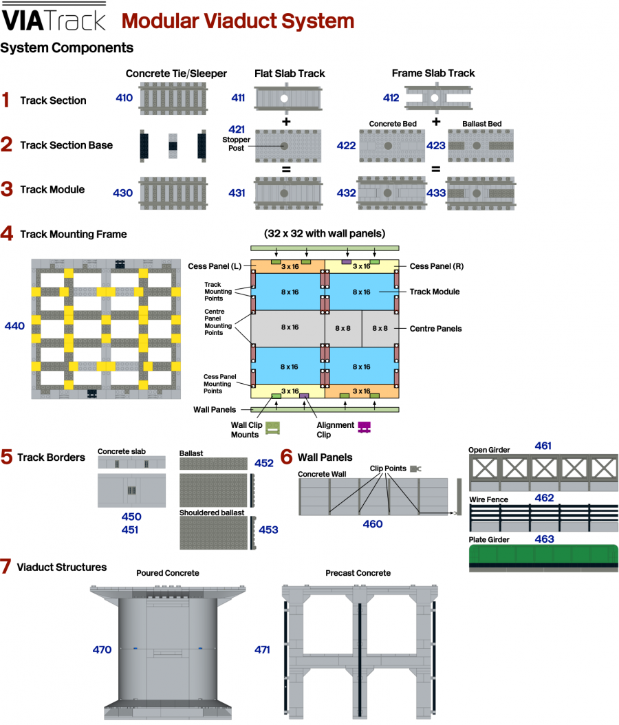
The ViaTrack system consists of 7 key components:
1. Track sections - this includes models of slab, and open slab concrete track as well conventional ballasted track
2. Track section bases - carriers for track sections
3. Track modules = 1 + 2
4. Track mounting frame - acts as substrate for the track modules, track borders, and clip-in wall modules
5. Track borders - various styles of cess and 6-foot way panels
6. Wall panels - clip in wall sections of various styles
7. Viaduct structures - various styles of viaduct civil engineering including poured and pre-cast concrete and brick arch
There are a wide variety of elements to choose from when building a railway based on ViaTrack. Elements can be chosen to best match a particular regional prototype or simply to add variety and interest to your layout.
Instructions of the various system components will be released in the Reference Instructions section.
