Difference between revisions of "Standard:Reference Track Configurations"
| (5 intermediate revisions by the same user not shown) | |||
| Line 4: | Line 4: | ||
== Parallel Curves == | == Parallel Curves == | ||
| + | |||
| + | The L-Gauge track system has 5 recognized standard radii implemented directly with available track products. These radii maintain 16-stud adjacent track centreline spacing. Complete circles are made from 16 curve track elements for the R40, R56, and R72 radii; each curve element occupying a 22.5º sector angle. Curve radii R88 and R104 are comprised of 32 curve track elements, each occupying a 11.25º sector angle. | ||
[[File:RefParallelCurves.png|288px]] | [[File:RefParallelCurves.png|288px]] | ||
== Reverse Loops == | == Reverse Loops == | ||
| + | |||
| + | Reverse loops are a convenient method of reversing the direction of travel of a complete train. The loops are illustrated returning to an adjacent parallel track; however, they can all easily be adapted to return to a common arrival/departure track with the addition of a switch and a R40 return curve. It is not recommended to use a common arrival/departure track with 9V or metal track because of the reversal of track polarity that occurs. This can be avoided by substituting any element in the reverse loop with an equivalent plastic track element to serve as an electrical isolation gap. | ||
=== R40 Reverse Loop === | === R40 Reverse Loop === | ||
| Line 27: | Line 31: | ||
== S-Bends == | == S-Bends == | ||
| − | === Lateral Offset: 16 Studs === | + | S-bends are a useful track configuration to achieve a lateral shift of centreline or to introduce an aesthetic alternative to tracks following strictly orthogonal alignment. S-bends are characterized by their lateral offset (shift of centreline) and transition length (distance required to perform lateral shift). Most of the S-bends presented here conform to 8-stud grid interval alignment; however, a few are aligned to a less conventional 4-stud grid interval. |
| + | |||
| + | === Lateral Offset: 16 Studs / 8 Stud Grid === | ||
| + | |||
| + | '''Lateral centreline offset:''' 16 studs | ||
| + | '''Transition length:''' 104 studs | ||
[[File:RefSBend16.png|306px]] | [[File:RefSBend16.png|306px]] | ||
| − | === Lateral Offset: 32 Studs === | + | === Lateral Offset: 32 Studs / 8 Stud Grid === |
| + | |||
| + | '''Lateral centreline offset:''' 32 studs | ||
| + | '''Transition length:''' 96 studs | ||
[[File:RefSBend32.png|306px]] | [[File:RefSBend32.png|306px]] | ||
| − | === Lateral Offset: 64 Studs === | + | === Lateral Offset: 64 Studs / 8 Stud Grid === |
| + | |||
| + | '''Lateral centreline offset:''' 64 studs | ||
| + | '''Transition length:''' 144 studs | ||
[[File:RefSBend64.png|387px]] | [[File:RefSBend64.png|387px]] | ||
| + | |||
| + | === Lateral Offset: 52 Studs / 4 Stud Grid === | ||
| + | |||
| + | '''Lateral centreline offset:''' 52 studs | ||
| + | '''Transition length:''' 144 studs | ||
| + | |||
| + | [[File:RefSBend52.png|384px]] | ||
| + | |||
| + | === Lateral Offset: 92 Studs / 4 Stud Grid === | ||
| + | |||
| + | '''Lateral centreline offset:''' 92 studs | ||
| + | '''Transition length:''' 192 studs | ||
| + | |||
| + | [[File:RefSBend92.png|481px]] | ||
| + | |||
| + | === Lateral Offset: 104 Studs / 8 Stud Grid === | ||
| + | |||
| + | '''Lateral centreline offset:''' 104 studs | ||
| + | '''Transition length:''' 176 studs | ||
| + | |||
| + | [[File:RefSBend104.png|450px]] | ||
== Crossovers == | == Crossovers == | ||
| + | |||
| + | Crossover junctions are a very common and useful configuration seen on real prototype railways. Typically, a crossover will be placed between two adjacent parallel tracks. Unfortunately, due to the geometric design of the LEGO® switch, crossover track configurations cannot be implemented between conventional 16-stud separated parallel running lines. Crossovers can only be implemented between parallel tracks separated by 32-studs. This can be achieved in two ways shown below using either two R40 curves or a single full straight track between the switches. Crossovers with 16-stud centreline separation can be made by modifying the LEGO® switch; however, that is an Expert topic requiring physical cutting and modification of the switch. | ||
[[File:RefCrossovers.png|290px]] | [[File:RefCrossovers.png|290px]] | ||
| + | |||
| + | == Return Curves == | ||
| + | |||
| + | Return curves are typically used to make parallel offset sidings adjacent to a running line. Using the 5 available curve radii, it is possible to make several offset intervals that are grid-aligned. | ||
| + | |||
| + | [[File:RefReturnCurves.png|385px]] | ||
== Diagonal Track == | == Diagonal Track == | ||
| Line 63: | Line 107: | ||
[[File:RefJunctionCrossing.png|609px]] | [[File:RefJunctionCrossing.png|609px]] | ||
| − | == | + | == Yard Sidings == |
| + | |||
| + | === Grid Aligned Yard Ladder === | ||
| + | |||
| + | [[File:RefYardLadder1.png|673px]] | ||
| + | |||
| + | === Compact Non-Aligned Yard Ladder === | ||
| + | |||
| + | [[File:RefYardLadder2.png|673px]] | ||
| + | |||
| + | === Grid Aligned Diagonal Yard Ladder === | ||
| − | [[File: | + | [[File:RefYardDiag.png|1138px]] |
Latest revision as of 15:19, 7 May 2015
The reference track configurations shown below can be useful for layout planning purposes or for just gaining greater insight into the LEGO® track system geometry. The configurations shown are all intended to be built using standard/unmodified track products. Almost all configurations conform to the conventions of 16-stud parallel track separation and nominally aligning to an 8-stud or 16-stud grid interval.
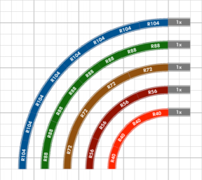
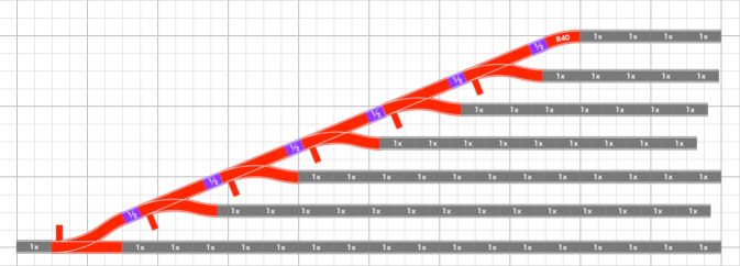
The track diagrams are illustrated in schematic form for easy interpretation. All diagrams have a superimposed 8-stud grid for interpretation of scale and for recognizing baseplate boundaries. Straight sections of track typically use the "standard" length 16-stud section shown as "1x"; these can represent LEGO® brand 9V or RC straights or the ME Models full straight. Some diagrams show "1/2" and "1/4" length straight sections representing the ME Models half straight and a single LEGO® flex track segment respectively.
Parallel Curves
The L-Gauge track system has 5 recognized standard radii implemented directly with available track products. These radii maintain 16-stud adjacent track centreline spacing. Complete circles are made from 16 curve track elements for the R40, R56, and R72 radii; each curve element occupying a 22.5º sector angle. Curve radii R88 and R104 are comprised of 32 curve track elements, each occupying a 11.25º sector angle.
Reverse Loops
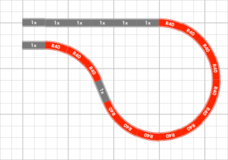
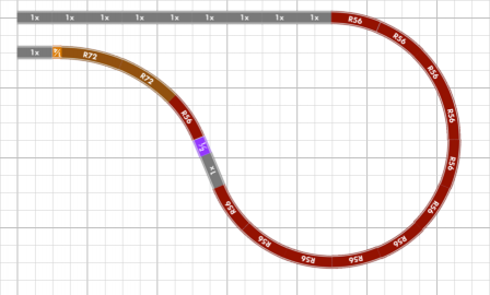
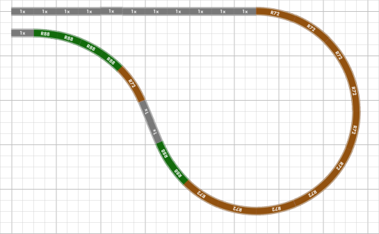
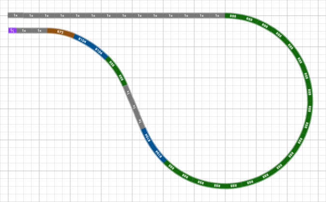
Reverse loops are a convenient method of reversing the direction of travel of a complete train. The loops are illustrated returning to an adjacent parallel track; however, they can all easily be adapted to return to a common arrival/departure track with the addition of a switch and a R40 return curve. It is not recommended to use a common arrival/departure track with 9V or metal track because of the reversal of track polarity that occurs. This can be avoided by substituting any element in the reverse loop with an equivalent plastic track element to serve as an electrical isolation gap.
R40 Reverse Loop
R56 Reverse Loop
R72 Reverse Loop
R88 Reverse Loop
S-Bends
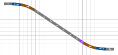
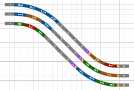
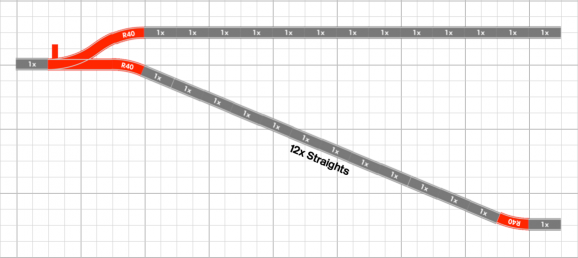
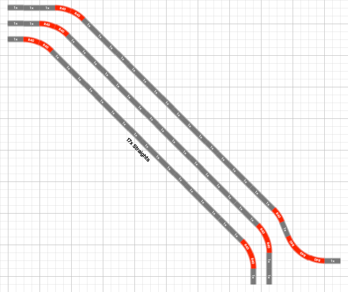
S-bends are a useful track configuration to achieve a lateral shift of centreline or to introduce an aesthetic alternative to tracks following strictly orthogonal alignment. S-bends are characterized by their lateral offset (shift of centreline) and transition length (distance required to perform lateral shift). Most of the S-bends presented here conform to 8-stud grid interval alignment; however, a few are aligned to a less conventional 4-stud grid interval.
Lateral Offset: 16 Studs / 8 Stud Grid
Lateral centreline offset: 16 studs Transition length: 104 studs
Lateral Offset: 32 Studs / 8 Stud Grid
Lateral centreline offset: 32 studs Transition length: 96 studs
Lateral Offset: 64 Studs / 8 Stud Grid
Lateral centreline offset: 64 studs Transition length: 144 studs
Lateral Offset: 52 Studs / 4 Stud Grid
Lateral centreline offset: 52 studs Transition length: 144 studs
Lateral Offset: 92 Studs / 4 Stud Grid
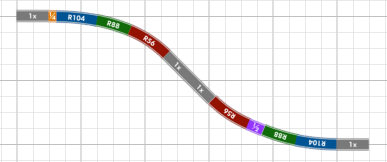
Lateral centreline offset: 92 studs Transition length: 192 studs
Lateral Offset: 104 Studs / 8 Stud Grid
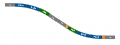
Lateral centreline offset: 104 studs Transition length: 176 studs
Crossovers
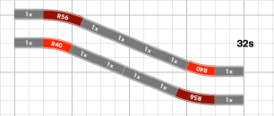
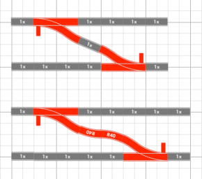
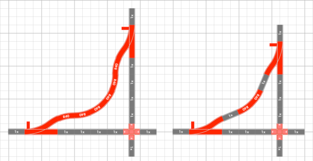
Crossover junctions are a very common and useful configuration seen on real prototype railways. Typically, a crossover will be placed between two adjacent parallel tracks. Unfortunately, due to the geometric design of the LEGO® switch, crossover track configurations cannot be implemented between conventional 16-stud separated parallel running lines. Crossovers can only be implemented between parallel tracks separated by 32-studs. This can be achieved in two ways shown below using either two R40 curves or a single full straight track between the switches. Crossovers with 16-stud centreline separation can be made by modifying the LEGO® switch; however, that is an Expert topic requiring physical cutting and modification of the switch.
Return Curves
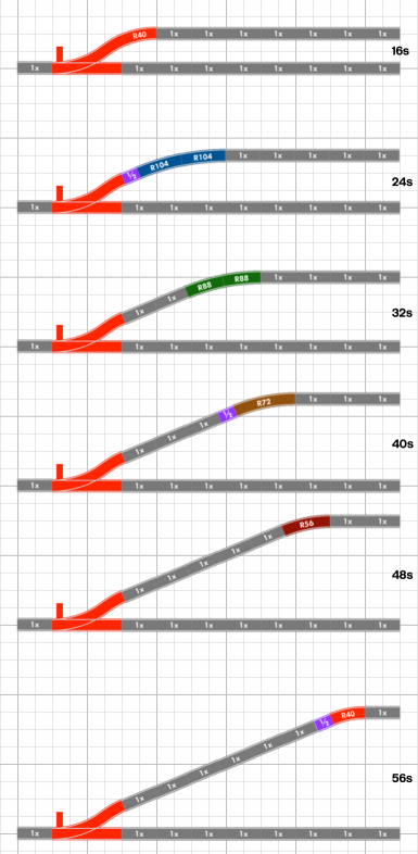
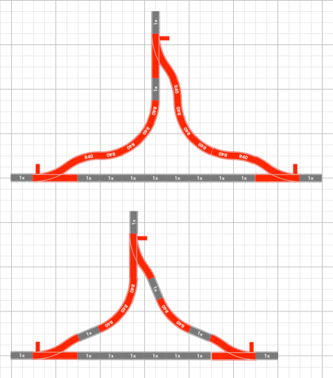
Return curves are typically used to make parallel offset sidings adjacent to a running line. Using the 5 available curve radii, it is possible to make several offset intervals that are grid-aligned.
