Difference between revisions of "Standard:Reference Track Configurations"
| Line 42: | Line 42: | ||
[[File:RefCrossovers.png|290px]] | [[File:RefCrossovers.png|290px]] | ||
| + | |||
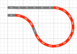
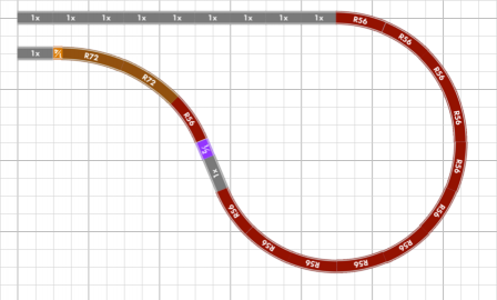
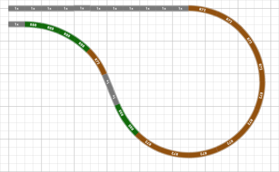
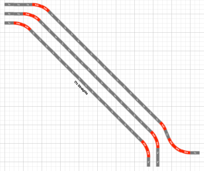
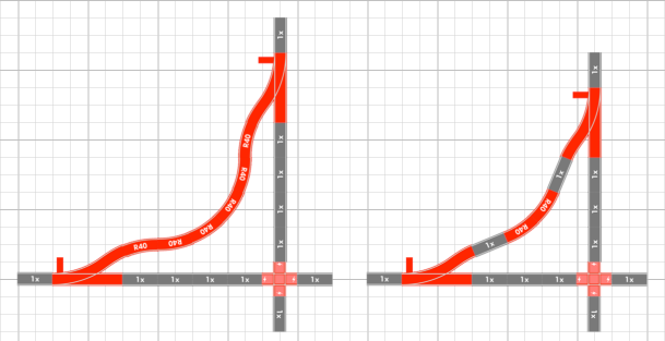
| + | == Return Curves == | ||
| + | |||
| + | [[File:RefReturnCurves.png|385px]] | ||
== Diagonal Track == | == Diagonal Track == | ||
| Line 62: | Line 66: | ||
[[File:RefJunctionCrossing.png|609px]] | [[File:RefJunctionCrossing.png|609px]] | ||
| − | |||
| − | |||
| − | |||
| − | |||
Revision as of 13:37, 7 May 2015
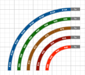
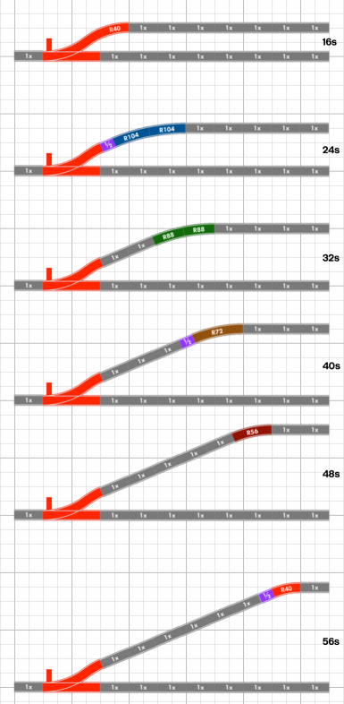
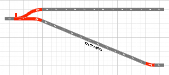
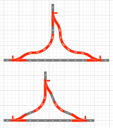
The reference track configurations shown below can be useful for layout planning purposes or for just gaining greater insight into the LEGO® track system geometry. The configurations shown are all intended to be built using standard/unmodified track products. Almost all configurations conform to the conventions of 16-stud parallel track separation and nominally aligning to an 8-stud or 16-stud grid interval.
The track diagrams are illustrated in schematic form for easy interpretation. All diagrams have a superimposed 8-stud grid for interpretation of scale and for recognizing baseplate boundaries. Straight sections of track typically use the "standard" length 16-stud section shown as "1x"; these can represent LEGO® brand 9V or RC straights or the ME Models full straight. Some diagrams show "1/2" and "1/4" length straight sections representing the ME Models half straight and a single LEGO® flex track segment respectively.
